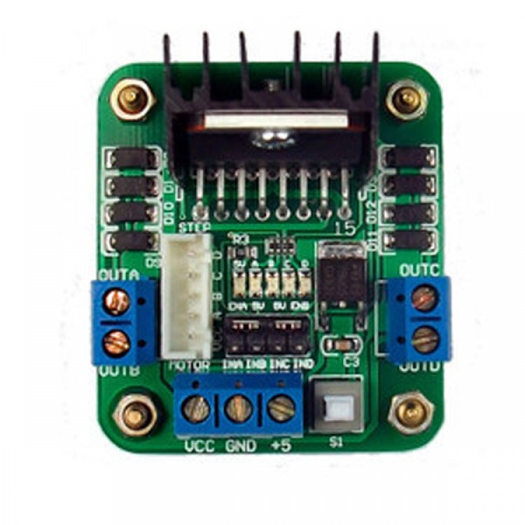

Remember, you can use any controller you’d like (Arduino, Raspberry Pi, etc) as long as it has at least two digital output pins and one PWM pin (per side). Now that you understand the logic behind your motor driver, it’s time to make the L298N motor driver connection with Arduino. This stand-alone board is designed to safely drive solenoids, relays, stepper motors, DC motors, and other inductive loads using TTL logic levels. Step 2: Connect the L298N motor driver to Arduino. For more info about the pin (I/P 1, 2, 3, 4) see above photos. The L298N is a dual full-bridge high current motor driver.I/P 3, 4: These pins control the direction of DC motors 2.I/P 1, 2: These pins control the direction of DC motors 1.EN B: It will control the speed of DC motor 2, by removing the jumper(so, PWM is enable).EN A: It will control the speed of DC motor 1, by removing the jumper(so, PWM is enable). Uses ST' L298N chip, can directly drive two 3-30V DC motor, and provide a 5V output interface, power for 5V single-chip circuitry, supports 3.If a 5V-EN jumper is removed, this pin act as an input(means the module is required 5v for logic enable). 5v(Logic power supply): It is an input and output terminal, If a 5V-EN jumper is in place, this pin acts as output and provide 5v from voltage regulator on board.Vs: This pin is used to provide a positive power to a motor driver module/devices.


Connect to PWM output for DC motor speed control. OUT 3, OUT 4: terminals are used to connect a Device(DC motor 2). Leave this in place when using a stepper motor.OUT 1, OUT 2: terminals are used to connect a Device(DC motor 1).


 0 kommentar(er)
